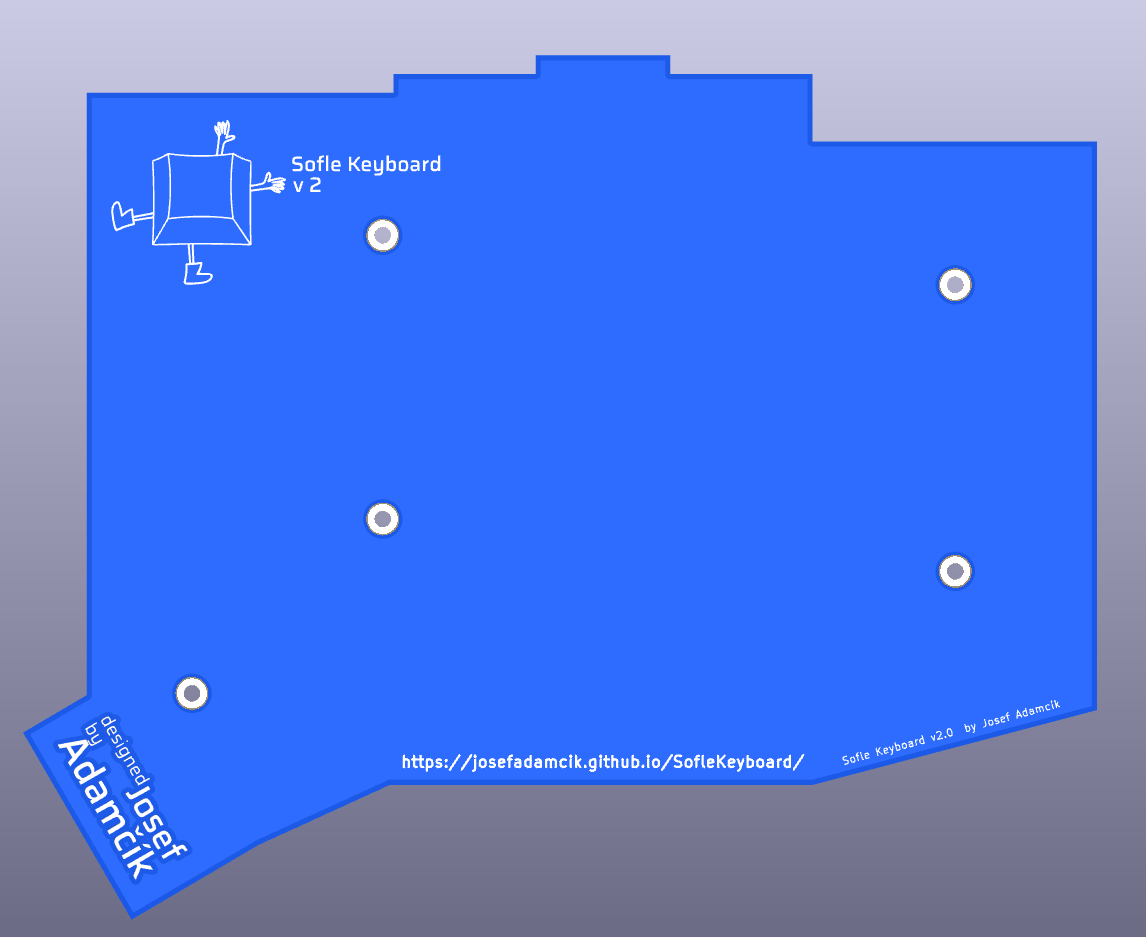
Sofle Pico Build log
These notes were made in KiCad during the design & build process. There were ultimately 4 produced iterations to get things dialed in. Mostly a personal punch list.
First Draft, V3.1
- NOT RELEVENT: (REPLACE WITH DIFFERNT OLED) Increased annular ring size for 32x128 stacked oled. (This footprint will be replaced by a 64x128)
- DONE: Swap in the correct oled
- DONE: Removed pico pads & rebuilt teardrops
- WONT DO: Update communication from serial to TX/RX. Maybe add the optional I2C back in, with better jumpers nad markings? (ARM spli boards do not support I2C. Half duplex/Serial comm is recommended. Left a pin open to expand to TX/RX in the future)
- DONE: (Mostly) TRRS/TRS jack is all loosey goosey. Go back to TRRS jack that is asymetrical for stability.
- WONT DO: Move components out from under the Pico so it can be drag soldered (The off-brand Picos don’t support this, plus we want the picos all facing down)
- DONE: Modify pico holes to account for off-brand Picos.
- DONE: What to do about pico led? Maybe split out to double footprint again? (Added double footrpint so the LED always faces down)
- DONE: The RH Oled is under the pico. Respect the board outlines (Moving to new OLED style fixes this)
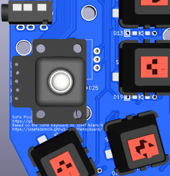
- DONE: Add puck footprint
- DONE: Add level shifter bypass
- DONE: After moving Oled and trrs, add 3rd hole for OLED plexi screen protector
- DONE: Does the vsys diode have an orientation?(Validated orientation matches the Junco)
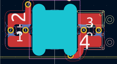
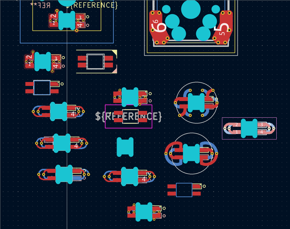
- DONE: The hotswop sockets and LEDs are in a single combo footprint. This is great for design, but a PITA for automated production. Need to create a placebo to generate proper PNP/BOM files. (Used a “dummy” footprint). The sk6812mini-e’s require ‘standard’ assembly, which is a large upcharge.
V3.1 -> 3.2
- Notes to self: The Pico variants are pretty fat. The pico outline is flush with the double sided OLED footprint. The double sided oled footprint sides can be seperated a bit if need be.
- DONE: Validate that the first sk6812 acts as a level shifter, then remove the level shifter bypass. (THis doesn’t work - they overheat the boards)
-
DONE: Consider removing volt shifter. Really hard to solder, may not be necessary. (Testing shifter bypass to asses SK6812 instead of SK6803) (DONT DO THIS! THE BOARD OVERHEATS)
- Lessons learned 5-22-23:
- DONE: Remove OLED pin markings after prototype validation
- DONE: The 4 holes in the keyplate need to be smaller, otherwise the posts go through, and that sucks.
- DONE: Make a hole in the bottom plate for the tenting puck to recess into.
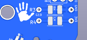
- DONE: Adding the unused pins to breakouts next to thumb.
- WONT DO: Moving LED junk where pimaronit tie in is now.
-
DONE: When preparing keyplate pcbs, add the gold rimmed footprint. Currently its an extra big hole on the keyplate layer for the spacer to pass through.
- WONT DO: Enlarge plate below thumb to accomodate space bars in plank layouts
- DONE: Tweak keyplate holes for OLEDs as they moved a bit between v3.02 and v3.03
- DONE: when writing FAQ link to tenting punk on printables.ocm
V3.2 -> 3.3
Improvements made while building prototype 3.02, included in version3.03
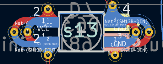
- OLEDs incorrectly wired. GP6 went to SCL, and GP7 went to SDA, when those two should have been switched. Fixed,
- OLED jack moved -y 2.54*1.5 for visual balance.
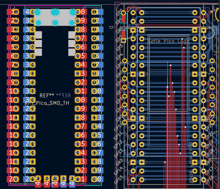
- Pico footprint made through-holes for buttons wider and moved bottom hole down
- Pico flipped footprint so now pico jack faces board. THen flipped it back, so reset button is always accessible.
- Pico - fixed rectangular gnd pads (now square)
- Added more visible markings to LED ground (Outline marking was obscured by solder/pad
- Reduced LED tweezer placement hole size from 1.5mm to 1mm
- Added breakouts for unused pins.
- Shrunk jumper plates. (Not sure if we’re keeping those)
- Enlarged puck hole for 3d printed tenting pucks
- Moved thumb post hole between switches rather than above, so its like Sofle v1 &v2, also helps hide screw head.
- Modified OLED footprint to support both types of 128x64. (GND & VCC are switched)
- Added help text for OLEDs
- Center oled plate holes for round outline
3.7795 is the keyplate multiplier when creating Fusion 360 imports
3.3 -> 3.4
Improvements made while building prototype 3.03, included in version3.04
- CONSIDER: Adding jumpers that route from the TRRS control pins on the Pico to unused pins, so that if someone pulls out a TRRS cable and burns out a pin, the Pico can be salvaged by re-flashing TRRS to a different pin.
- DONE: 5-pin MX footprint fit validated.
- moved diode labels
- Removed Solenoid (Left it in blueprint to install on a backplate)
- Updated branding
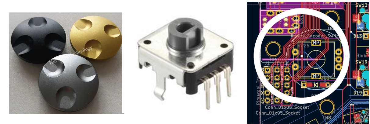
- Explored moving the rotary encoder farther from thumb cluster to allow for ‘low profile’ encoder knobs on EC12’s. There is not enough room. (That particular encoder knob is 29mm). Added this feature to the list for Pico Zero features.
- Considered collapsing the 4 separate footprints for the two types of OLEDs into a set of 2 footprints, and then OLED type is set with a jumper - OR - dropping one OLED type for a single type with single footprint with handedness set by jumpers like the legacy Sofles. Decided against this, as it increases build complexity for the end user. The downside, is it complicates the case options because there is a 3mm placement difference between left and right OLEDs. If the acrylic OLED cover is used, this should not be noticeable. If 3d printing a case, the right/left sides will have minor differences to account for this gap.
- Considered pushing the Pico footprints farther apart, allowing for a headerless drag solder install & automated PCB manufacture. Decided against it due to increased manufacturing costs of the larger board. The increase in board size is not much, maybe 3mm-5mm, but having those pads close together may make hand drag soldering difficult? Also not sure if omitting the bottom through holes would be acceptable for automated assembly.
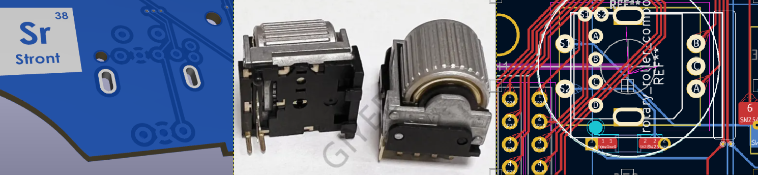
- Considered adding a USB C jack in addition to TRRS. (Example can be seen in the Stront). This would allow for automated pcb assembly, and much cooler cables than can be found with TRRS. There’s not enough room - unless the patch bay is omitted. I like the patch bay. Added this feature to the ‘nice to have list’.
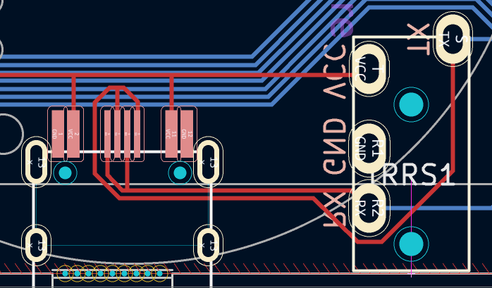
- Considered adding horizontal rotary encoder/ec12 encoder combo as seen on the Stront. The horizontal encoder requires a notched edge cutout.which would require drastic re-routing, and may increase production cost. Added to the ‘nice to have list’.
- Agonizing over attribution placement.
- Spent far too much time dialing in the logo lockup. I’m stubborn and don’t want to pay an Adobe subscription, so I did the text lockup in KiCad. Looking at other split keyboards. I really want a vertical lockup because of the visible logo in the coppers - but horizontal supports the attribution blurb better.
![]()
- Submitted a github issue requesting input from the Sofle main contributors. In response to the question:
“should the LEDs be omitted in favor of combo MX/choc footprints like the Sofle V1? The drag soldering required for the level shifter & and the non-standard SK6803 makes the build more difficult.”
Oh, and the last question: I have personally never built nor used a keyboard with RGB lighting. I am just not interested in it. So if it was just about me, I would drop the RGB support.That said, it was the most common change request for Sofle V1/V2 and the main reason for Sofle RGB made by Dane Evans. But it is indeed a conundrum because the Choc version was the second most common request for Sofle V2 and that’s why we have the version from Brain Low.
I decided to keep the RGB & OLED in this variant:
I appreciate the input on the RGB. As a touch typist - i don’t really use the RGB & OLED - but those features were what drew me to the Sofle initially. I think the Sofle is a really great first board for people new to the hobby. I’ve tried to make this variant extra easy to solder and used accessible parts, in hopes that it would entice others to try it out. I’d like to keep the RGB in this version, and eventually, build a 2040 zero based version that drops the RGB in favor of supporting both choc & MX, along with a horizontal OLED. (I love the idea of a horizontal screen for a keymap ‘cheat sheet’ - i think that would be great for people transitioning into the split world).
-
user @uberrice was gracious enough to provide a peer review. Revised annular ring widths to clear JLC minimums.
-
11-6-2023: Regenerated Bom/PNP/Gerber and submitted an order for v3.4.4. (Shipping was 2x as expensive today?)
3.4 -> 3.5
- 11-8-23: Got a notification from JLC that there are ‘too many slots’ and an additional fee will be charged. I canceled the order. (It’s only $5 USD extra - but thats a 50% price bump!) The fee probably stems from using ‘edge cuts’ to cutout the LED holes. I had a similar issue with the Junco v1.1, and swapping out mechanical through holes for edge cuts in the footprint resolved the fee. (It’s also alleged this fee is not charged consistently, based on who reviews your board at JLC). Based the new led design on the cutouts found in this x-switch footprint & the unreleased zerf9 by freznel.
- Checked via settings for other popular boards:
| Board | Hole Width (mm) | Via dia (mm) |
|---|---|---|
| Sofle V1 | .3 | .4 |
| Sofle V2 | .3 | .4 |
| Sofle RGB | .3 | .4 |
| Sofle Choc | .3 | .4 |
| Corne Classic | .4 | .6 |
| Corne Choc | .4 | .6 |
| Helix | .4 | .6 |
| Lily 58 | .4 | .6 |
| Stront | .4 | .8 |
| Piantor | .3 | .6 |
| Chunky | .3 | .6 |
It looks like 3/6 is a safe bet. Reworked the led footprint to accommodate. Mode the vias out from between pads to prevent shorts from sloppy soldering. Sent out v3.5 for production 11-13-23.
v3.5.1 11-14-23
- Uberrice was kind enough to review again:
- Updated LED footprint to remove potential acid trap.
- Removed routing on GND net since it’s using a polygon. (best practice!)
- Converted logo text to svg->footprint so it will transfer well between mac/pc. Had to add an exclusion zone for the text only logo in the copper. Rebuilding zones was creating an outline around the footprint. I tried making the footprint part of the zone, but it still wouldn’t connect. :shrug:.
- Increased the line weight of the GND pin markings on the LEDs. (In it’s currents state, it is easily obscured by solder paste).
- Considered moving the middle thumb key to allow 1.25u keycaps. The switch would need to move ~2.5mm. Decided against this, because no other Sofle boards do this, and it would require tweaking the bottom outline.
- OLED footprint GND pins made square. Increased font size on OLED pin markings.
- Tried to indicate handedness via matrix intersection - realized matrix is a full 5x6 block with no unused intersections.
- Updated OLED logo using image2cpp:
- Added QMK/VIA logo to RH to appear on boot:

v3.5.2 12-15-23
-
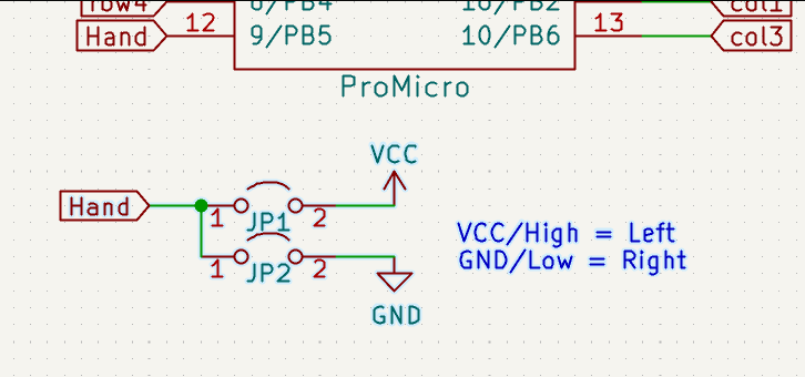
Found an example of handedness by pin in a Lotus58. The GND and VCC tie directly into those pins - specifically, not using a pull up resistor.
-
Since the drilled LED holes don’t circumvent the ‘too many holes’ fee, I refactored the led footprint and pulled them out.
-
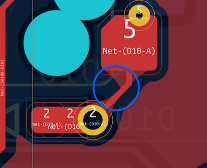
Using automatic teardrop generation created acid traps between the diode and the switch pad. Revised the diode footprint to add a through hole below the switch pad.
Before:
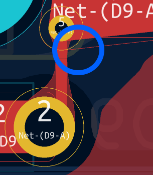
Unsuccessfully tried adding extra pad to the switch:
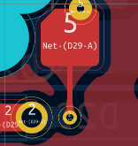
Added extra pad to the diode:
- Started a reddit thread to figure out if the pimaroni is just jenky, or if i’m doing it wrong. It looks like the Pimoroni is just jenky. I’m abandoning support, but making notes in the repo so that someone else can fix it if they want to. There are other threads complaining about this issue.
-
Moved the patch bay up by 2mm to make room for the Pimoroni.
-
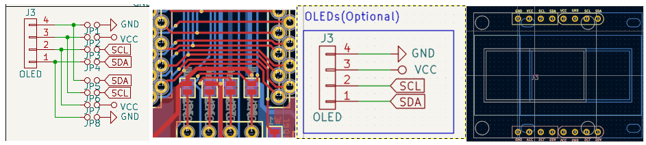
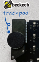
Looked into Cirque trackpad - it looks viable, and easy? Beekeeb sells a breakout board that plugs right into the I2C Oled holes for Sofle. I ordered one to try it out. (12-18-23). I did poke-yoke the OLED holes by removing the masking on one side - that might cause issues with the breakout board orientation - but I don’t think so, based on how the Sofle V2 jumpers are oriented.
- Found and removed dummy placeholder footprints for LED PCBA that were breaking the .step export. (Probably inherited from Sofle Choc?)
- Updated the bypass jumper footprint to make it easier to use.

-
- Thermal imaging LED measurement A redditor suggested that the level shifter could be omitted, because the first LED would do the same job. After consulting the Junco owner, the math says the SK6812 will pull too many amps. The Sk6812 is preferable because it’s more common/available, so it’s at least worth a try. Using a Fluke TiS50, (resolution 220x165) I compared 3 variants, taking measurements sporadically over three hours.
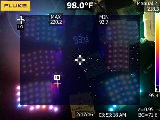 | LED | level shifter | Average operating temp | image | | — | ————- | ———————- | —– | | SK6803 MINI-E | Y | ~120°F / 48°C |
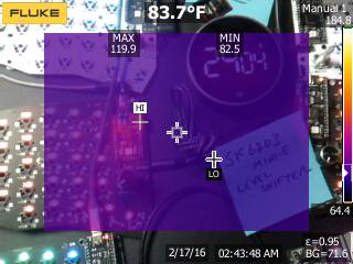 | | SK6803 MINI-E | N | ~130°F / 54°C |
 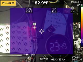 | | SK6812 MINI-E | N | ~230°F / 110°C |
 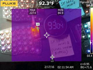 |
|
Thermal imaging LED test conclusion
The SK6812 ran too hot. It overheated and shut down a few times. The SK6812Mini-e should not be used. The average run temp for the SK6803 Mini-e was about 6°C difference with/without the level shifter. The Picos operating range is -20°C to 85°C, so even running without a level shifter puts us at 54°C, well within the acceptable range. Updating the build guide with level shifter as ‘recommended, but not required’.
- Reduced default QMK max brightness: In QMK
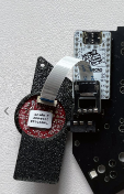
info.json, reducingrgb_matrix.max_brightness: 127down from255reduced the operating temp of the level-shifter SK6803MINI-E down to ~100°F. This seems like a much better default. Didn’t try it with the bypass jumper variant though. - Power circuit refactor: existing circuit was cribbed from Junco. There is a diode between VBus and Vsys. This diode gets hot. It looks like that is not needed, because there is an internal diode between vbus and vsys. According to the docs, the hand plugged into USB gets 5v, and then I can output 3.3v through vsys. The other hand takes in that 3.3v through the Vsys pin. The the RP2040 docs(pg15) recommend adding a shotkey diode before the VSYS pin for that other hand, so if both hands are plugged into USB, there won’t be an issue. Based on this video, I could try using a 1N5817 Shottky diode. (Cheap, through hole, readily available). However - that would add additional complication. Plan A is to remove the VBUS connection entirely, and go vsys-vsys.
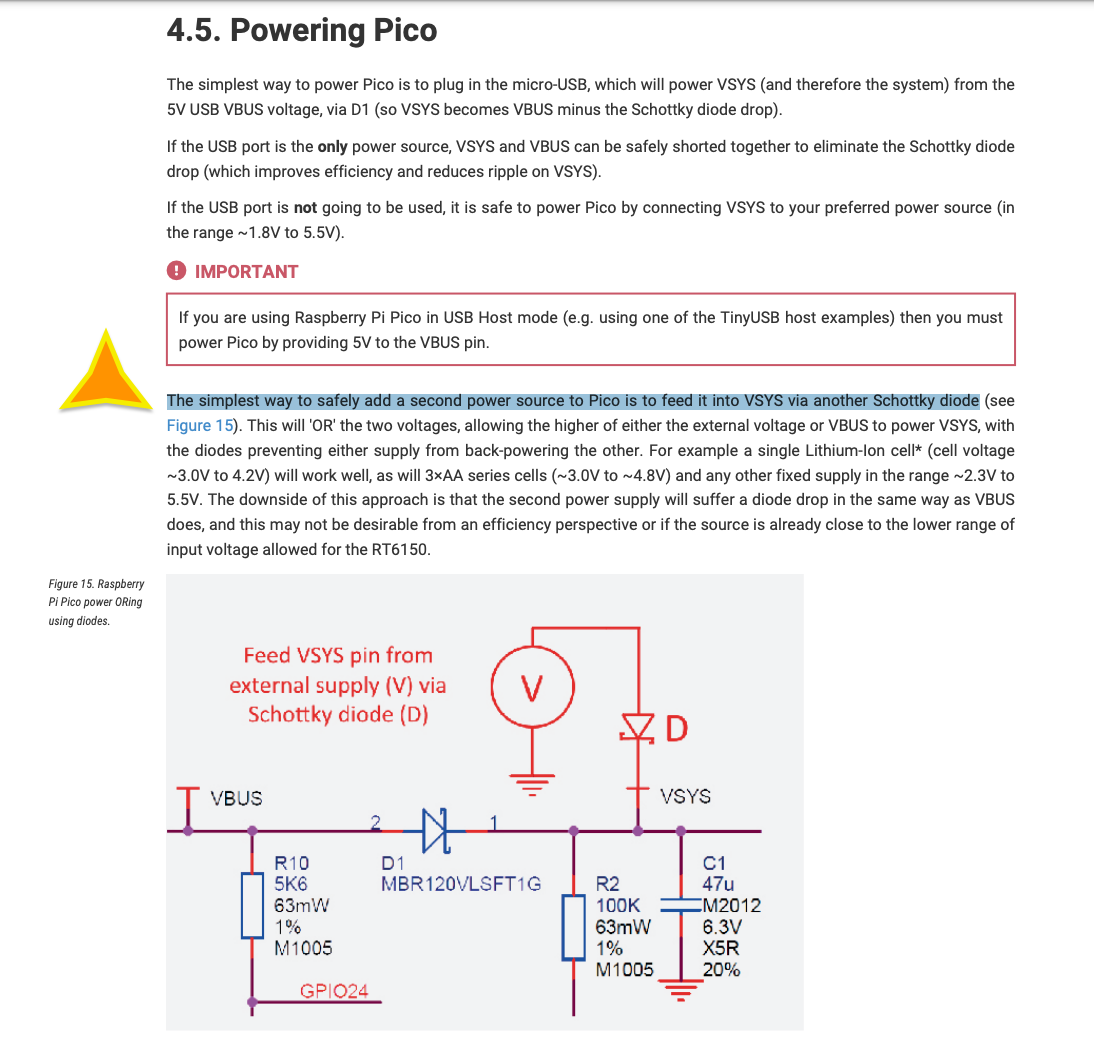 pico_internal_diode_vbus_vsys.png
- Submitted new file for production 12-28-23.
Sofle_Pico_v3.5.3_12-27-23.zip
v3.5.4
- Discuss VBUS->VSYS diode removal with Dane. (It’s possible that the diode is required for Pico clone flavors?). After testing v3.5.2, it was determined the diode is required for some clones, but can be omitted if using an ‘offical’ Pico. Dane had decided against using a Schottky there to simplify the circuit.
- Validate the circuit revisions and thermal profile for v3.5.2. NOT WORKING! While there is a schottky diode between VBUS and VSYS on the official Pico - some clones do not have the diode. No power will make it to the diodes or other hand.
- Added a power diode back in. (SChottky this time). Hoping that the updgrade to IN5817 from a standard 1N4148 will improve the thermal profile.
- I didn’t want to wait for a new board to validate the power circuit revisions - so I pulled the 1N4148 diodes off of a working v3.5.0 board and measured the heat. It looks like the IN5817’s are a vast improvement. I updated the docs to include these. It’s noteworthy that the level shifter made almost no difference on the heat - except the hotspots are now on the outermost LED’s and not the MCU.
| Level Shifter | Power Circuit Diode | Brightness % | Hight Temp | Image |
|---|---|---|---|---|
| Yes | 1N4148 | 50% | 98°F | 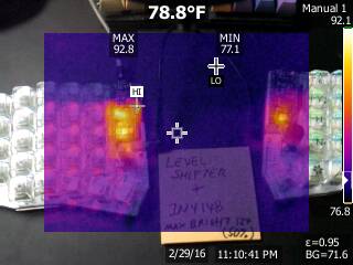 |
| Yes | 1N4148 | 100% | 140°F | 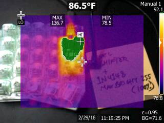 |
| Yes | 1N5817 | 50% | 91°F | 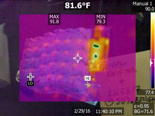 |
| Yes | 1N5817 | 100% | 108°F | 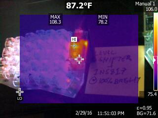 |
| No | 1N5817 | 50% | 91°F | 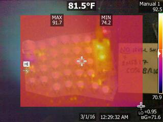 |
| No | 1N5817 | 100% | 110°F | 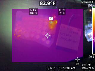 |
- Tried to get the 23mm Circque trackpad working. It doesn’t work - but I want the option to continue development in the future, so i added a footprint specifically for the trackpad.
- Via Support added!
- The weAct variant moves pin 28, so handed pin detection won’t work. Moved the handedness pin to GP18.
- Considered adding an additional breakout for 5V, control, & GND to allow for Solenoid backplate tie in. The 5v VBUS input is pretty well isolated in the upper left. It would take a fiar bit of work to implement. Not gonna do it - it’s not fun anymore! :C
- While conducting thermal tests I connected USB cables to both sides at the same time. I burnt out the VBUS input on the lefthand board. :C This makes me think adding a patchbay tie in for VBUS is probably a dangerous idea. Not gonna implement it.
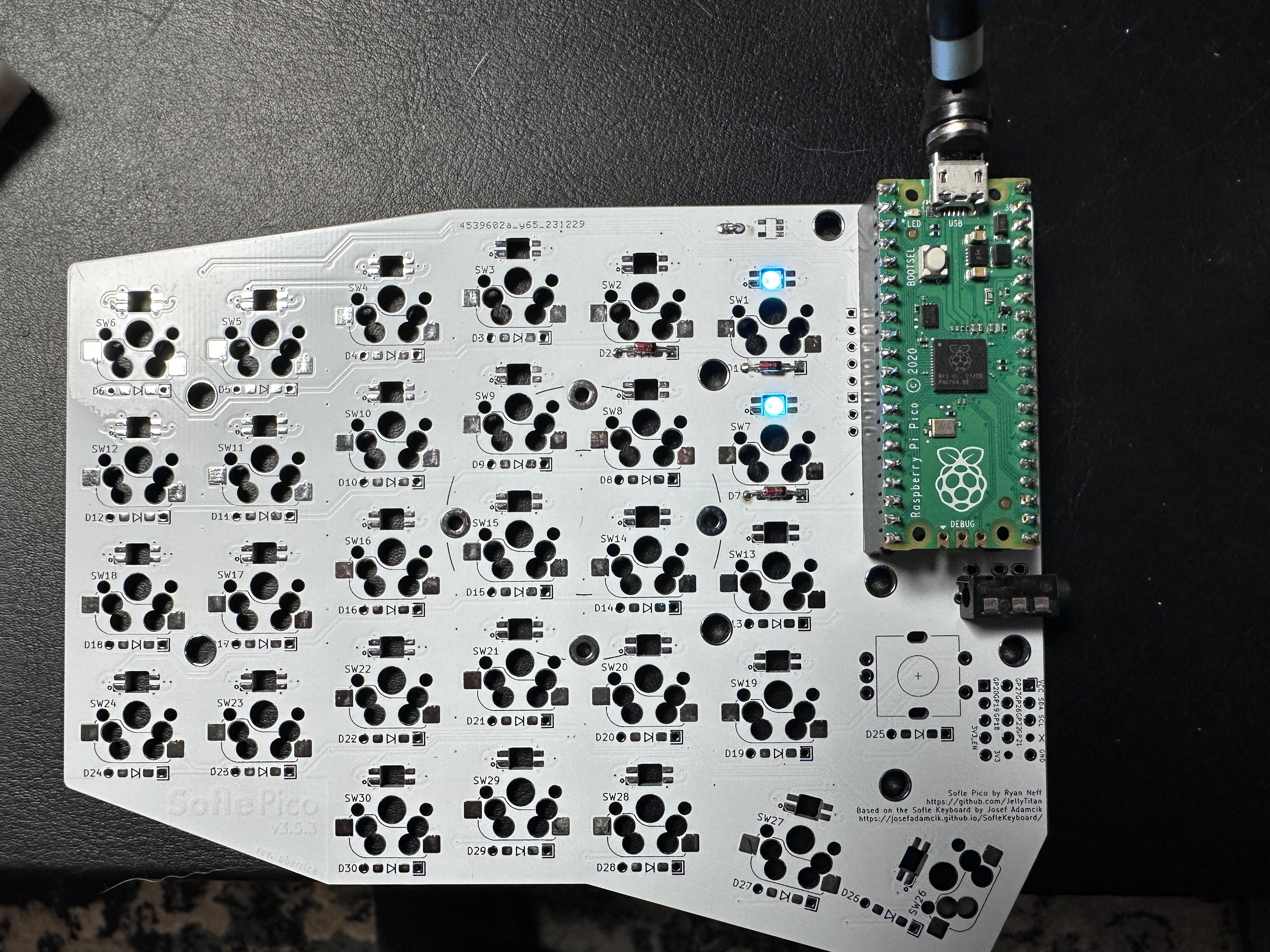
- Made switch numbering the same sequence as the LED connections to make debugging easier. This required a big schematic/pcb revision - splitting the Switch/LED footprint combos out into seperate footprints.
- Added tie in’s for cirque trackpad breakout boards. Even though i couldn’t get the cirque to work.
- Revised keyplate outline to accomodate the Cirque breakout board risers.
- Removed handedness pin from GP28. It would need a pull-up resistor, and I chose to omit that in lieu of flashing both hands seperately initially.
- Added GND plane stitching.
- Submitted new file for production 1-13-24.
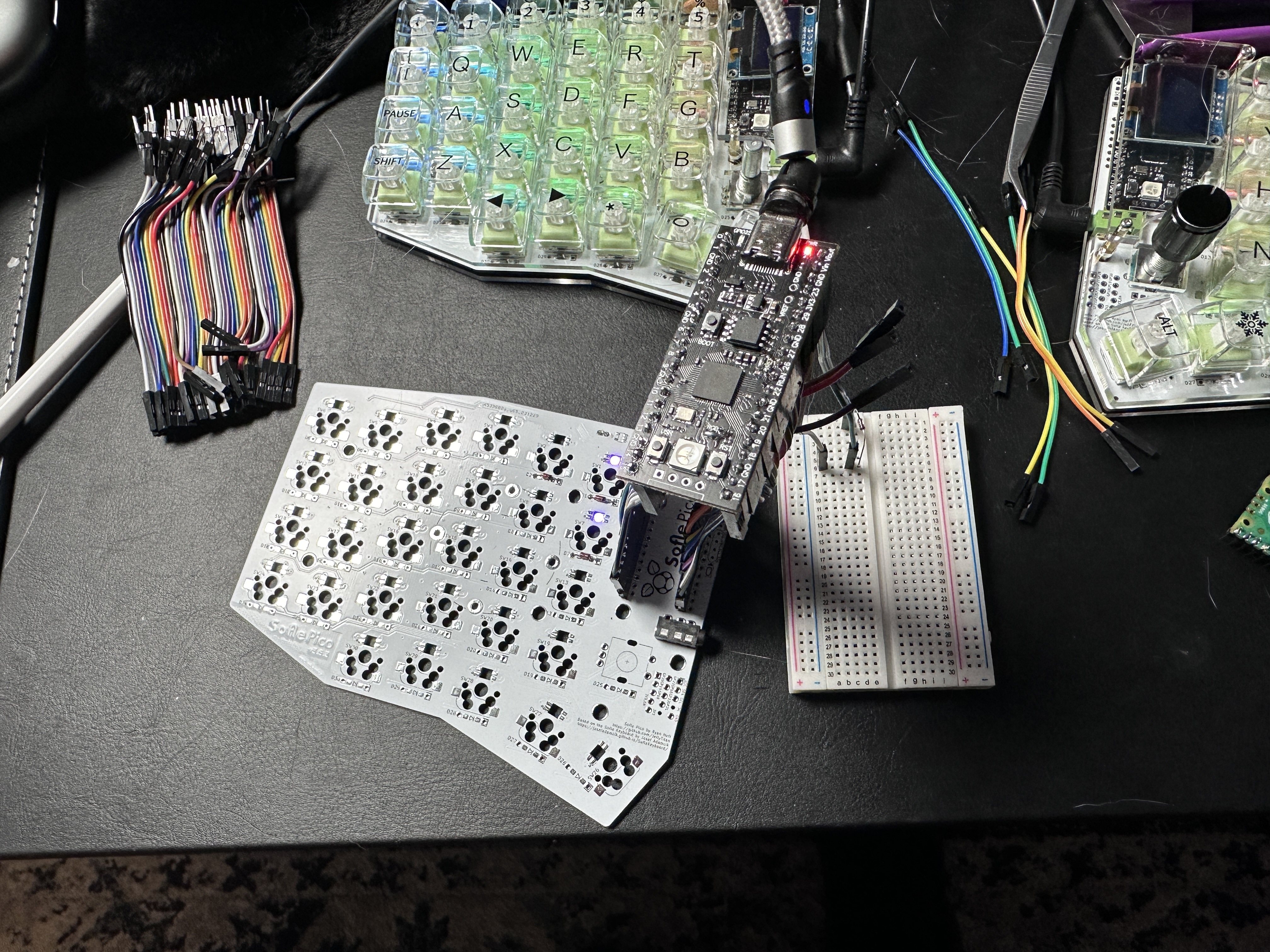
Sofle_Pico_v3.5.4_1-13-24.zip - Tested the prototype - it works! I’m calling tis the first stable release.
v3.5.5
Since the main PCB is stable, focusing on case and documentation.
- Reviewed the backplate branding for legacy sofles, decided to go more minimalist and de-emphasize the text.
Here’s what i went with instead:
- Simplified LED markings. (Saw this on theWerle’s choc variant)

- Removed logo on one side below MCU, and move attribution there, to free up space. @theWerle took care of this as part of the Sofle Pico Choc.
- @theWerle added a slew of new features with the Choc variant and a complete rework of the MX version:
- split-power protection PFET (Prevents shorts if you accidentally unplug a TRRS cable).
- Pull up resistors for the I2C bus. (Improves reliability).
- Patch bay improvements
- Added more SMD support
- Adds support for split handedness by pin
 Note - the QMK PR is still set to LH master by default - which may be prefered considering the split power protection.
 - Improved routing
- Adds opitional decoupling capacitors for power smoothing.

- Level shifter removal
v3.5.6
- Added part number placeholders for JLC and PCBWay to both Pico & Pico Choc.
- @todo add lables for handedness by pin to both sides.
-
Future Feature Wish list
- Color displays.
- USB-C in addition to TRRS (Maybe a ‘low-cost’ version with solder only switches & RP2040 Zero?)
- Solenoid backplate (Would need rp2040 zero for 5v)
- Piezo speaker (QMK doesn’t support this for ARM boards yet)?
- Horizontal encoder/ec12 encoder combo. (The horiontal encoder needs additional cutouts - there isn’t room for those with the base Pico)
- Move ec12 encoder out a bit to allow for 30mm low-profile knobs.
- Add a ‘handedness pin’ for qmk auto-detection. (Can’t do via current matrix - matrix is full on both sides).
- Put a GND plane on both sides, wire VCC directly. (with big fat traces)!
- Round bottom screw mount of OLED plate. (With the current component layout, this would obscure the patch bay.)
- Haptic buzzer? (https://github.com/GEIGEIGEIST/KLOR/blob/main/images/buildguide/haptic_solder.jpg)
- To prevent pin shorts caused by TRRS cable unexpected removal, maybe add an RJ45 jack footprint? There isn’t room on the current Sofle Pico, but maybe a RP2040 Zero based variant could support it? https://github.com/JellyTitan/Sofle-Pico/discussions/13