Soldering and workholding
There’s a few common soldering methods used with through-hole components. In this guide, we’ll be using the “work holding” method. Accordingly, the docs will not reference flipping the PCB over for soldering legs.
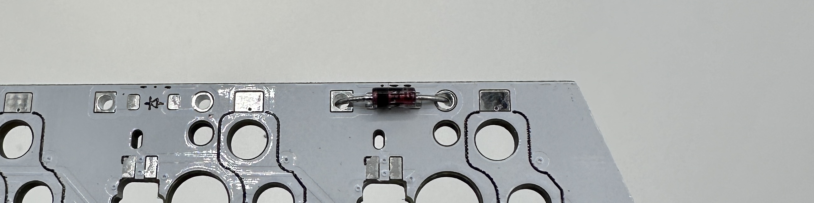
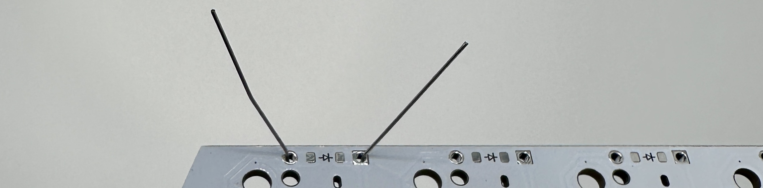
The bendy method
Push the legs through the holes, then bend the legs slightly outward on the bottom side to keep the component in the hole when the PCB is flipped over. Solder on the side of the board opposite from the side the component was inserted.
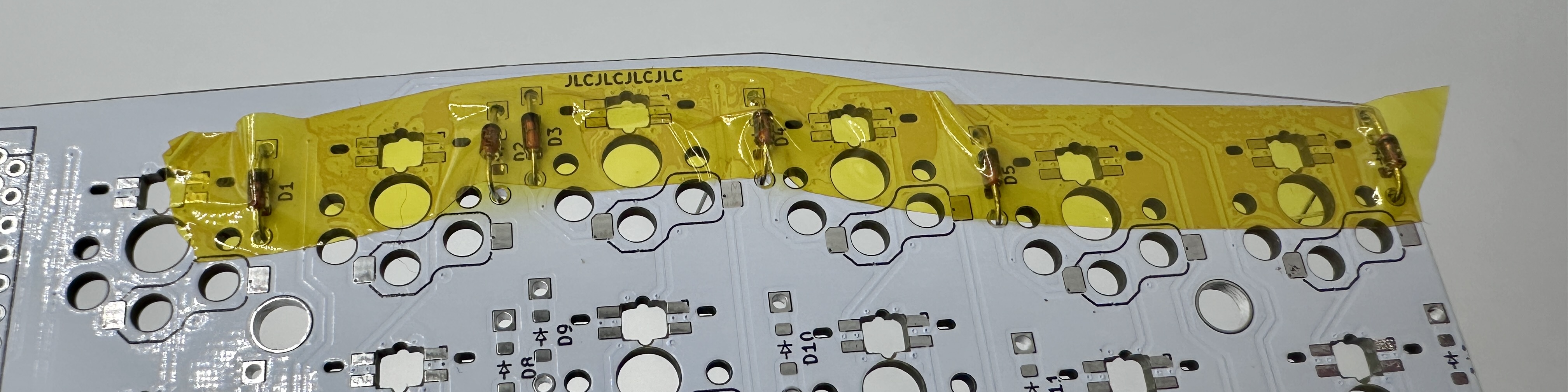
The tape method:
Push the legs through the holes and put a piece of kapton tape over the component to keep it in place when the board is flipped. Solder on the side of the board opposite from the side the component was inserted.
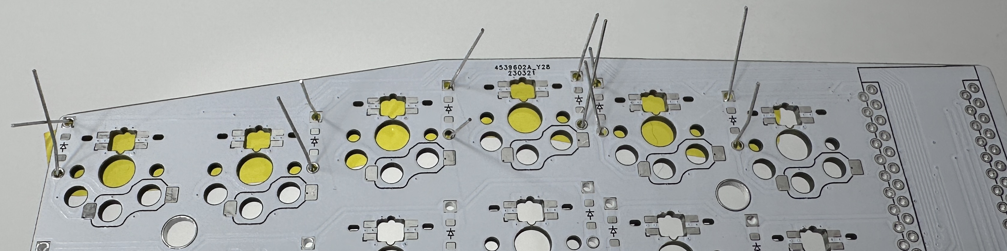
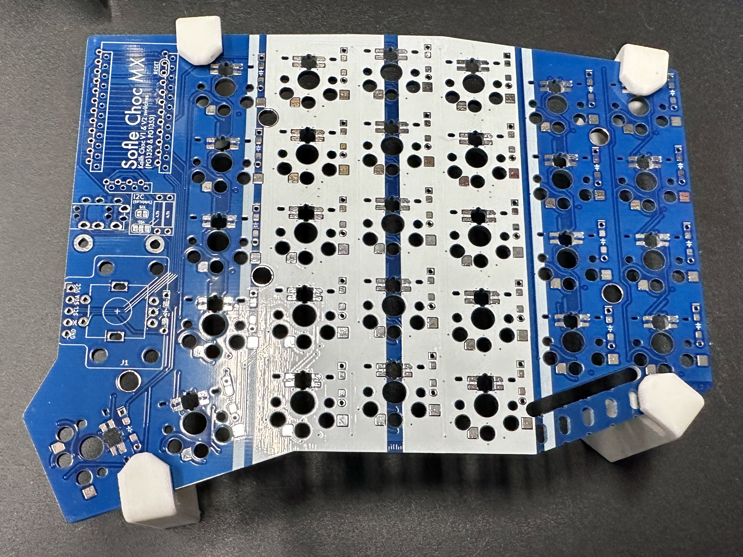
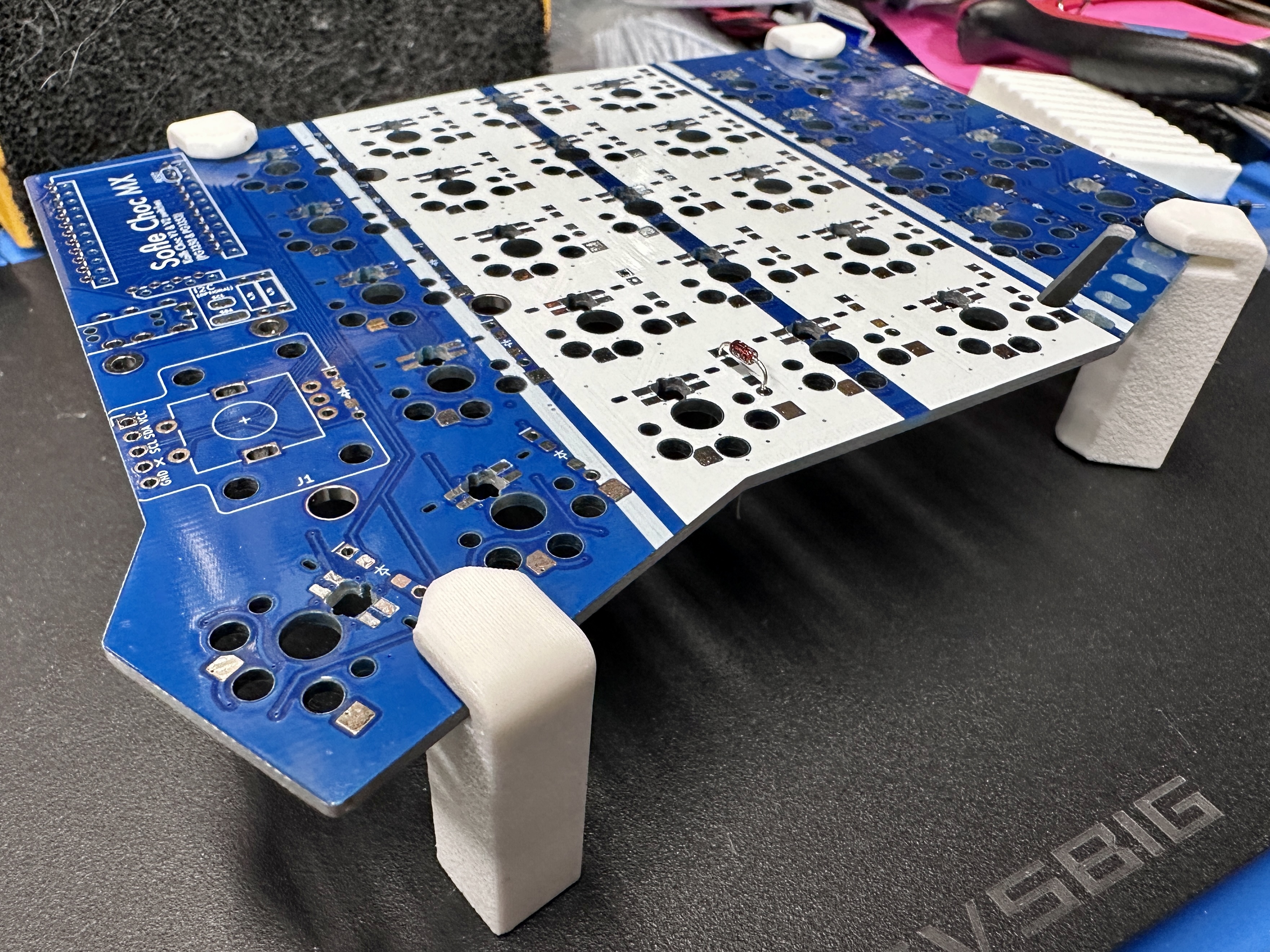
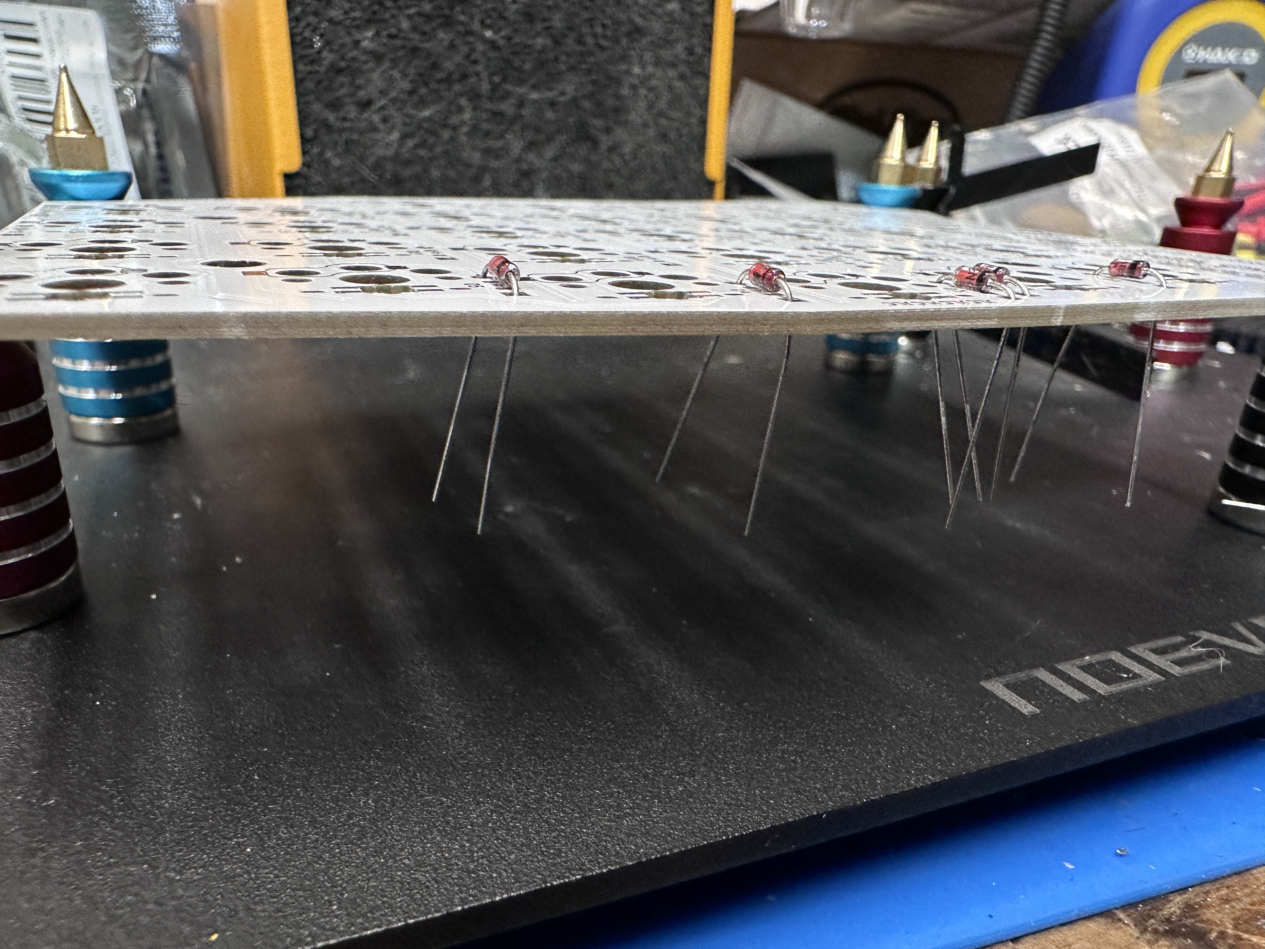
Work holding
Use helping hands or work holding jig to keep the PCB lifted off the work surface. Insert components through the holes, do not flip the pcb, and solder on the side the components are inserted.
This is the recommended method.
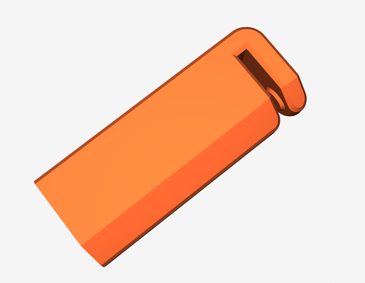
If you have access to a 3d printer, you can print disposable work holding legs designed specifically for the ErgoDonk Zero PCB.
Magnetic work holding thingies 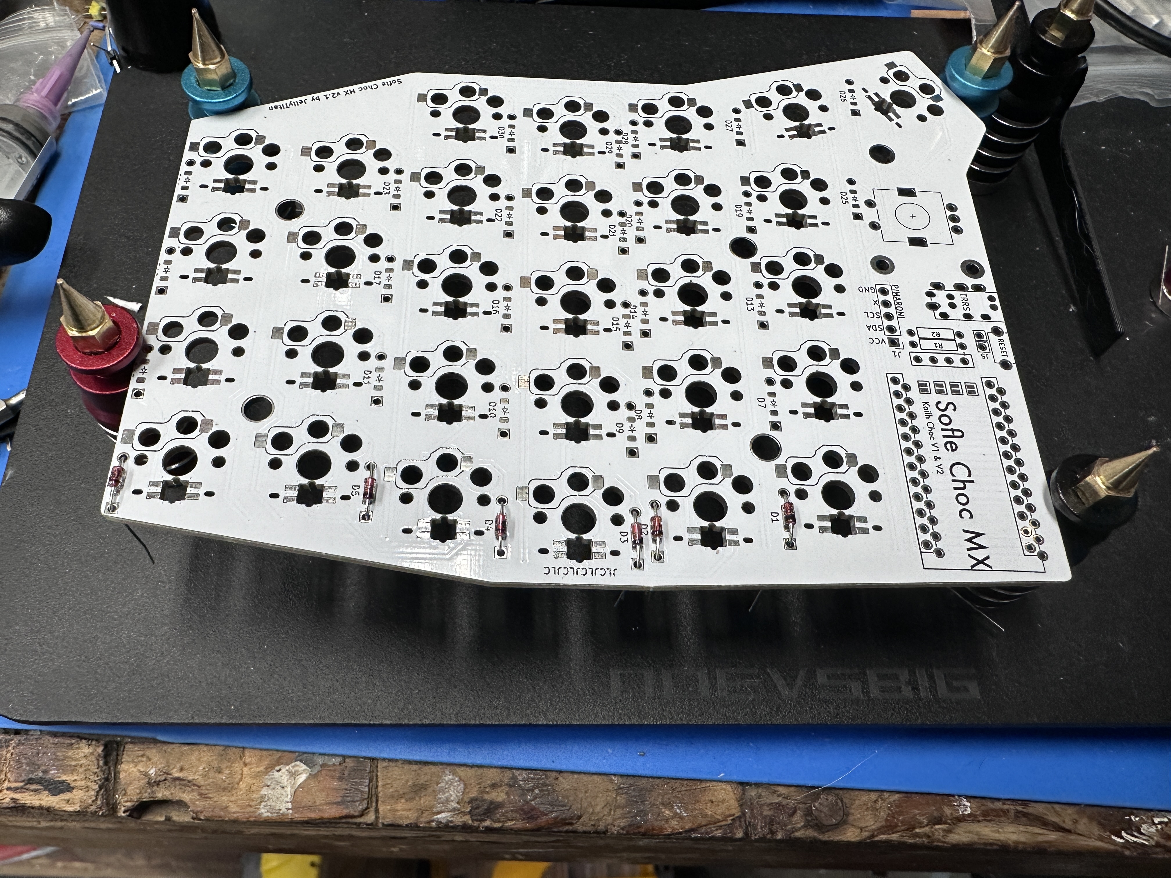
3d Printable work holding feet